
General-purpose bridge cranes are the most commonly used type. They are erected on rails on fixed span supports of buildings and are suitable for workshops and warehouses in factories and mines. Cranes can move materials, workpieces, or equipment within their rated load range, whether inside a factory or in an open area. Their biggest advantage is that they do not occupy a significant portion of the work area.
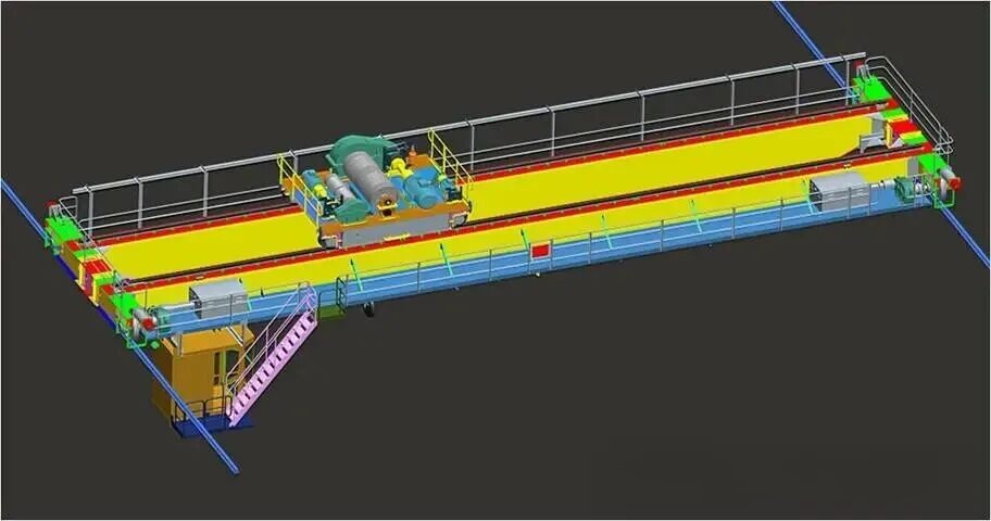
1. General Bridge Crane Structure
1.1 General Bridge Crane Components
A general bridge crane mainly consists of four parts: the bridge frame, the trolley, the crane traveling mechanism, and the electrical equipment.
The bridge frame is generally a double-beam structure composed of a box-type main beam and end beams. Rails are installed on the upper flange of the main beam for the trolley to travel on. When the main beam uses a narrow beam structure, the electrical control equipment is placed on a walkway beside the main beam; when the main beam uses a wide beam structure, the electrical control equipment is generally placed inside the main beam.
The trolley is the core component of the crane. The bridge frame has one or more trolleys, which can operate independently; multiple trolleys can operate individually or be designed to operate in tandem. The trolley is equipped with a hoisting mechanism and a traveling mechanism. The trolley traveling mechanism can be centrally driven or separately driven.
Crane traveling mechanisms are generally driven separately; some use two-corner drives, while others use four-corner drives.
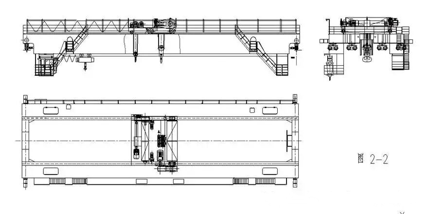
Figures 2-1 to 2-5 below show examples of various types of general-purpose bridge cranes, illustrating their general structure.
Figure 2-1 shows a small to medium tonnage low headroom crane.
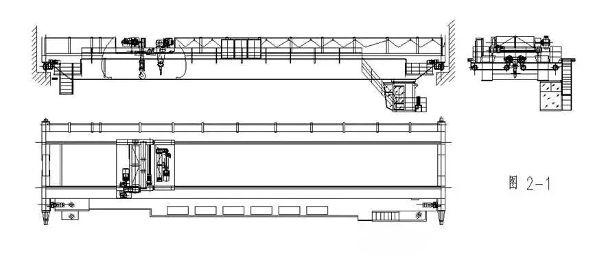
Figure 2-2 shows a large-tonnage, low-headroom crane.
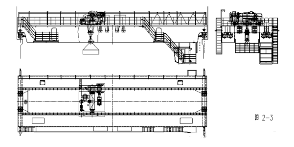
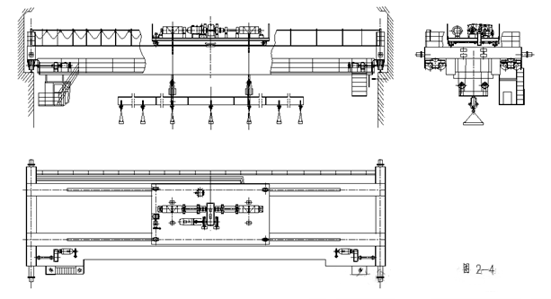
Examples of the structure of an electromagnetic bridge crane are shown in Figures 2-3 and 2-4.
The general structure of a grab bucket bridge crane is shown in Figure 2-5. 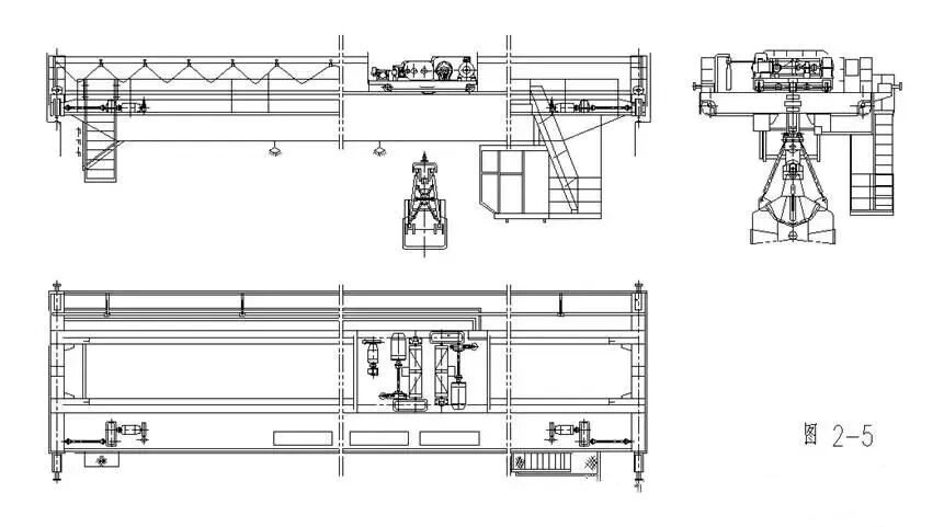
1.2 Trolley
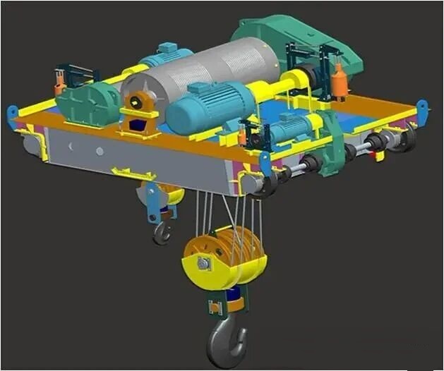
The trolley mainly consists of three parts: the hoisting mechanism, the trolley traveling mechanism, and the trolley frame. The trolley has different arrangements depending on the different usage requirements of the crane; please refer to the examples in Figures 2-1 to 2-7.
1.2.1 Lifting Mechanism
A lifting mechanism generally consists of a drive unit, a wire rope winding system, a lifting device, and safety protection devices. Some also use an electric hoist as the lifting mechanism.
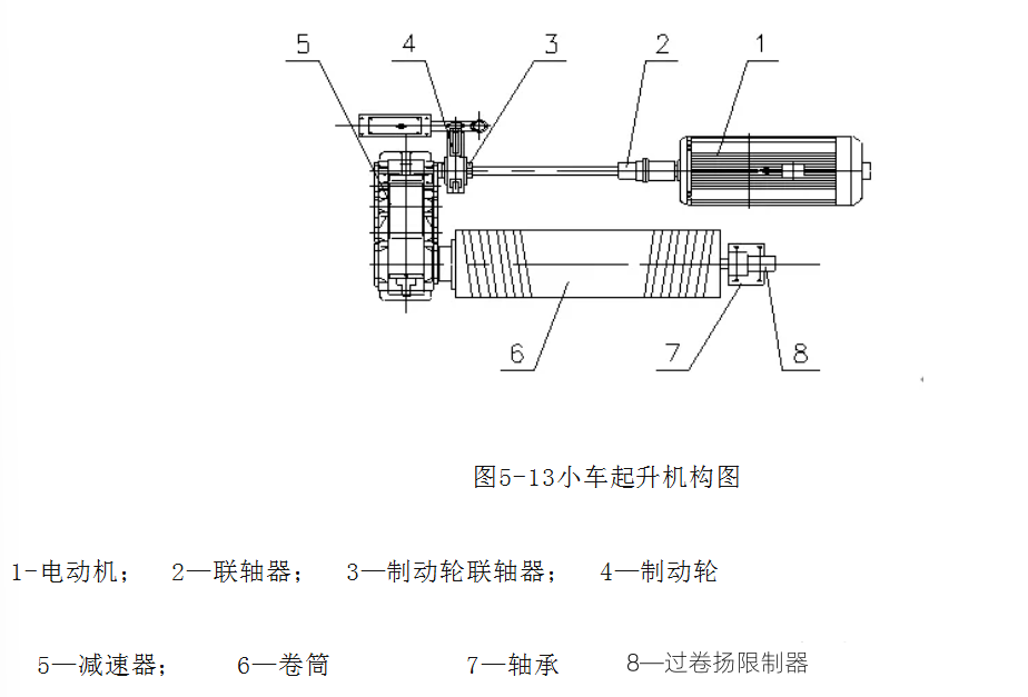
The drive unit includes components such as a motor, coupling, compensating shaft, brake, and reducer. When the drive unit uses conventional control or stator voltage regulation speed control, the motor is a wound-rotor type; when using frequency conversion speed control, it is a variable frequency motor.
The wire rope winding system includes the wire rope, drum, fixed pulley block (the balance pulley in the fixed pulley block can be replaced by a balance frame), and movable pulley block.
The lifting device includes a hook, grab bucket, lifting electromagnet, or hanging beam.
Safety protection devices include overload limiters and lifting height limiters.
The lifting mechanism is connected to the reducer via a coupling, and the low-speed shaft of the reducer drives the drum to rotate, which then drives the lifting device through the wire rope winding system. By controlling the forward and reverse rotation of the motor, the lifting device can be raised and lowered (grab bucket cranes include grab bucket raising, lowering, opening, and closing).
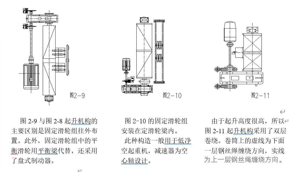
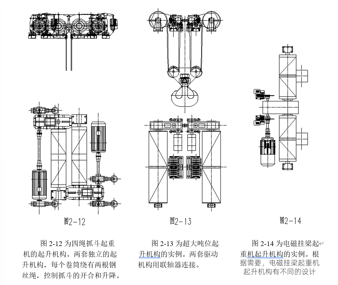
The composition of the lifting mechanism varies depending on the specific application requirements; Figures 2-9 to 2-14 provide some examples.
1.2.2 Trolley Traveling Mechanism
The trolley traveling mechanism mainly consists of a driving device and a running support. The driving device mainly consists of a motor, reducer, and brake. The running support mainly includes wheels and wheel balance beams.
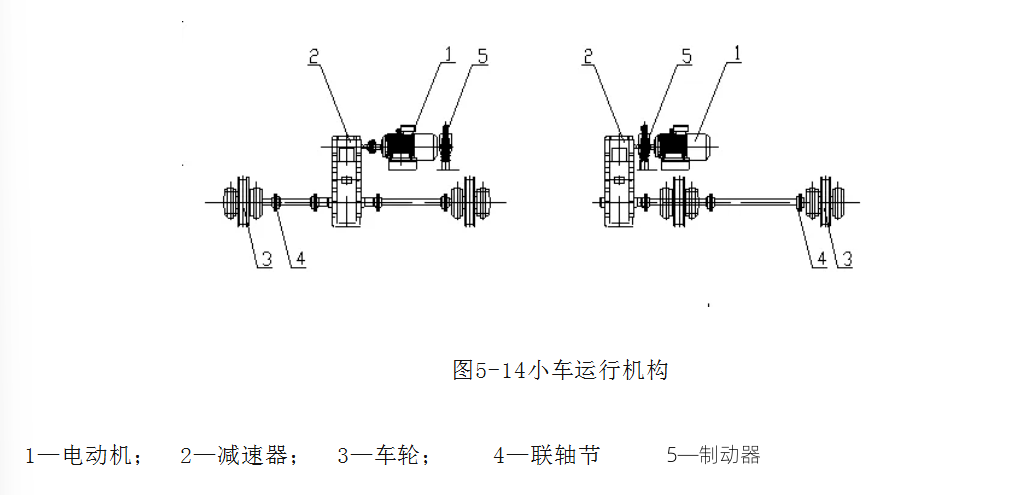
The trolley traveling mechanism uses centralized drive (see figure) or separate drive. Some large-tonnage cranes use wheel balance beams to reduce wheel pressure.
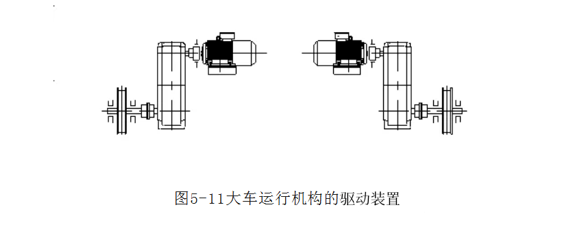
The driving device of the trolley traveling mechanism also has two forms. One is the traditional structure (see figure), where the motor drives a vertical reducer, and the low-speed shaft of the reducer drives the drive wheel. The other form uses a three-in-one driving device, where the motor, reducer, and brake are integrated, and the low-speed shaft of the reducer is directly mounted on the drive wheel axle or connected to the drive wheel axle via a coupling or compensating shaft.
For safe trolley operation, trolley travel limit switches and buffers are installed.
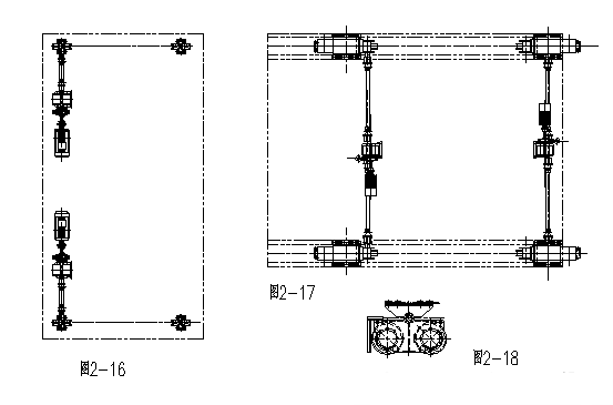
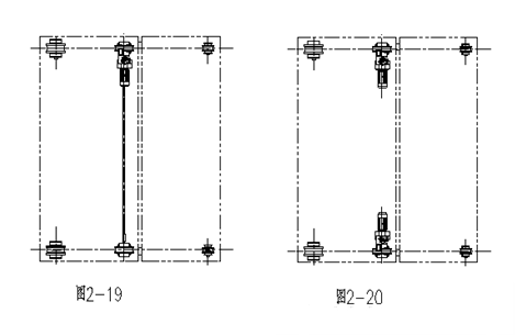
Depending on the specific circumstances, the trolley’s operation can be configured accordingly. Traditional drive systems include centralized drive (see Figures 2-15 and 2-17) and separate drive systems (see Figure 2-16). The same applies to three-in-one drive systems; Figure 2-19 shows a centralized drive system, and Figure 2-20 shows separate drive systems. For trolleys with large lifting capacities, additional wheels can be added, or a balance beam can be used; Figure 2-18 shows one type of balance beam structure.
1.3 Crane Traveling Mechanism
The crane traveling mechanism mainly consists of a travel drive unit and traveling supports. The travel drive unit mainly consists of a motor, reducer, and brake. The traveling supports mainly include wheels and wheel balance beams. Crane traveling mechanisms use separate drives, typically two or four sets of drive units. Traveling mechanisms with narrow beams are generally installed on the walkway of the bridge frame, while those with wide beams are generally installed at the ends of the main beam.
There are two types of drive units for the traveling mechanism: one is the traditional configuration (see figure), and the other uses a three-in-one drive unit (see Figure 2-22). When conventional or stator voltage regulation speed control is used, the motor is a wound-rotor type; when variable frequency speed control is used, the motor is a squirrel-cage motor or a variable frequency motor.
Large-tonnage crane traveling mechanisms use wheel balance beams to reduce wheel pressure. Horizontal wheels can also be added according to contract requirements.
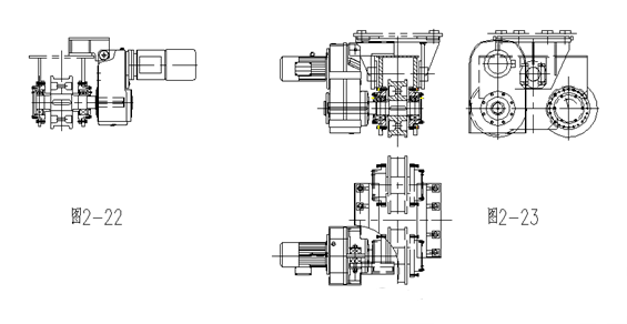
Figures 2-22 and 2-23 show examples of the three-in-one drive unit structure. Figure 2-22 shows the drive unit without a wheel balance beam, and Figure 2-23 shows the assembly with a wheel balance beam.
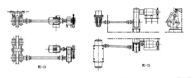
A traditional structure example of the drive unit without a wheel balance beam is shown in Figure 2-21. Examples of the structure with a wheel balance beam are shown in Figures 2-24 and 2-25. Figure 2-24 shows an example of a horizontal parallel shaft reducer with the motor arranged inwards, and Figure 2-25 shows an example of a vertical parallel shaft reducer with the motor arranged outwards.
Some large-tonnage cranes adopt the type shown in Figure 2-26, which is driven by one electric motor to drive two drive wheels.
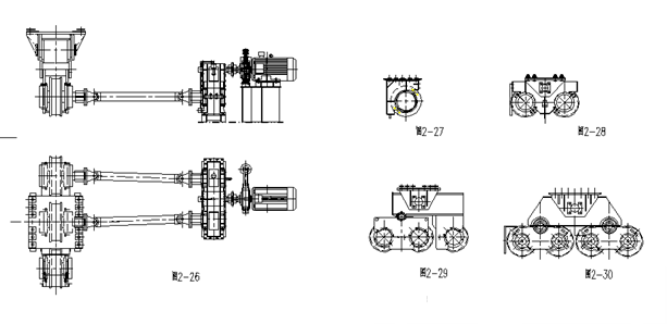
In the running support, small-tonnage cranes are equipped with two wheels on each end beam, or the wheel seats shown in Figure 2-27 are installed under the end beams. For large-tonnage cranes, different wheel balance beams or combinations thereof shown in Figures 2-27 to 2-30 are selected to support different loads.
1.4 Cable Tray
The cable tray is the main structure, serving as the installation foundation for the trolley, crane traveling mechanism, and electrical equipment. The cable tray mainly consists of the main beam, end beams, walkways, trolley cable hanger, trolley rails, maintenance platform and ladders, platforms, railings, and other components.
The cable tray is a crucial load-bearing component of the crane, possessing sufficient strength, rigidity, and overall stability to meet national standards and contractual requirements, ensuring the normal operation of the crane. After the overall machine test, when the unloaded trolley is in its extreme position, the camber of the main beam is not less than 0.7S/1000 (S is the crane span), and the maximum camber value is controlled within the range of S/10 at mid-span.
Depending on different requirements or situations, the main beam can be designed as a narrow box girder with standard rails (see Figures 2-4 to 2-7), a semi-offset box girder with standard rails, an offset box girder with standard rails (Figure 2-1), or a wide box girder with standard rails (see Figures 2-2 to 2-3). The main beam’s top cover is equipped with tracks for the trolley to run on. When the main beam is a narrow beam structure, a cooling electrical room is installed on the electrical equipment mounting platform when the ambient temperature cannot meet the normal operating requirements of the electrical equipment; the electrical room is equipped with a heat insulation layer. When the main beam is a wide beam structure, the electrical equipment is generally installed in an electrical room located inside the main beam. When the ambient temperature cannot meet the normal operating requirements of the electrical equipment, an air conditioning unit is installed in the electrical room, and a heat insulation layer is also installed in the electrical room.
1.5 Operator’s Cab
The operator’s cab is the workplace where the operator controls the crane. It contains electrical control equipment, lighting equipment, various instruments, and fire extinguishers.
There are two types of operator’s cabs: open and closed. Open cabs were used in workplaces with relatively good indoor environmental conditions, but are rarely used nowadays. Generally, cranes are equipped with closed cabs. Closed, cooled operator’s cabs are used in workplaces with high ambient temperatures.
Closed operator’s cabs feature a full field of vision structure with a bottom window at the front. The windows and doors use aluminum alloy frames with tempered safety glass. The interior features an adjustable soft seat that allows for constant observation of the operating status of various mechanisms, ensuring safe operation of the crane. The cab is covered with insulated rubber carpet. Concealed wiring is used, with connections between indoor and outdoor wiring via a terminal box for easy maintenance.
Closed, cooled operator’s cabs are equipped with air conditioning and have a double-layered insulation material filling structure.
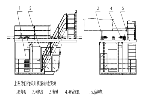
Depending on requirements, the operator’s cab can be installed in a fixed position on the cable tray or be a mobile operator’s cab. Mobile driver’s cabs can be further divided into self-propelled driver’s cabs and trolley-mounted driver’s cabs.
The structure of a trolley-mounted driver’s cab is as follows: the driver’s cab is connected to the trolley via a structural frame, and the driver’s cab moves synchronously with the trolley.
1.6 Electrical Room
The electrical room utilizes a wide-beam cable tray structure, typically located in the middle of one of the main beams. Sealed doors with locks and handles are installed at both ends of the electrical room. A passageway of at least 500mm is generally provided inside the electrical room, with the passageway surface covered by insulated rubber carpet.
When the ambient temperature is too high to meet the requirements of the electrical equipment, a cooling fan is required, with cool air delivered into the electrical room through ductwork. The interior walls of the electrical room are fitted with an insulation layer, filled with insulating material to reduce the impact of external heat.
The electrical room also houses lighting fixtures and a portable fire extinguisher.
1.7 Electrical Control Room
Generally a narrow-beam structure, the electrical equipment is mounted on the cable tray walkway. If environmental conditions do not meet the requirements of the electrical equipment, an electrical control room must be installed on the cable tray walkway. When the ambient temperature is insufficient for the electrical equipment, a cooling fan is installed outside the electrical control room, with cool air delivered into the electrical control room through ductwork. The electrical control room is fitted with an insulation layer, filled with insulating material to ensure the normal operation of the electrical equipment. The door to the electrical room is equipped with a lock and a handle. A passageway of at least 500mm is generally provided inside the electrical room.
Related Posts
What is an Electric Winch?
This electric winch is a motorized mechanical device. It utilizes an electric…
Festoon vs Conductor Bar: Which Power System for Your Overhead Crane?
Every overhead crane needs a way to deliver electrical power…