
I. Bridge Structure
The bridge frame of a bridge crane is a metal structure. It bears the wheel pressure of the fully loaded trolley on one hand, and on the other hand, transfers the entire weight of the fully loaded crane to the rails and building structure on the fixed span supports within the factory building via the traveling wheels supporting the bridge frame.
There are many structural forms for cable trays, including box-shaped structures, box-shaped single-girder structures, four-truss structures, and single-web open structures.
1. Box-shaped structures have a series of advantages such as simple manufacturing process, strong versatility, and convenient installation and maintenance, making them the most commonly used structural form both domestically and internationally (as shown in Figure 5-5). The main girder has two closed box-shaped sections, each with upper and lower cover plates and two vertical webs. The hoisting trolley track is fixed in the middle of the upper cover plate of the main girder. Another type is the off-center box-shaped structure, where the track is moved above the main web.
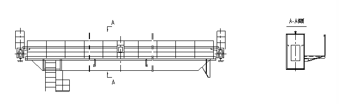
Figure 5-5 Box-shaped cable tray
2. The box-girder single main beam structure uses a single wide-flange box-girder main beam instead of two main beams, thus reducing its self-weight. It is a relatively new structural form (as shown in Figure 5-6).
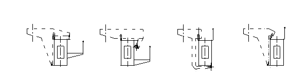
Figure 5-6 Box Girder Single Main Beam Cross Section
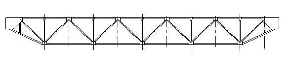
Figure 5-7 Four-truss bridge structure
3. Four-truss structure: The two main beams of the cable tray are closed spatial structures composed of four planar trusses. The vertical truss containing the trolley track is called the main truss, which bears the vertical load, while the other vertical truss is called the secondary truss. The main and secondary trusses are connected as a whole by horizontal trusses (as shown in Figure 5-7).
II. Main Beam of the Cable Tray The cable tray is a fundamental component of a crane. A double-beam cable tray consists of two main beams and two end beams. This section mainly introduces the main beams.
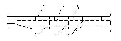
There are many structural forms for the main beams. Box-shaped main beams are widely used both domestically and internationally due to their advantages such as high overall rigidity and favorable manufacturing, assembly, and maintenance conditions (as shown in Figure 5-8). It consists of a closed box-shaped cross-section formed by an upper cover plate 1, a lower cover plate 2, and vertical web plates 3. To ensure sufficient stability of the upper cover plate and vertical web plates, various stiffening ribs and longitudinal angle steels are installed inside the box-shaped main beam. The entire main beam is a welded structure.
The main beam is mostly made of ordinary carbon steel Q235-B and Q235-C, and some are made of low alloy steel Q345. The low alloy steel does not help much in terms of the rigidity of the main beam. Cranes used in low temperature environments (-20°C to 25°C) are made of Q235-D or Q345.
1. Camber of the Main Beams
The two main beams that make up the bridge frame are both made into a uniformly upward-curved shape. The amount of upward camber is called the camber. The national standard GB/T14405-93 “General Bridge Cranes” specifies that the camber value at mid-span of the main beam is:
F=(0.9/1000~1.4/1000)S Where: F—camber; S—span of the main beam
Furthermore, the maximum camber should be controlled within (1/10)S of the mid-span (as shown in Figure 5-9). This camber should be measured under conditions without the influence of solar radiation or temperature differences.
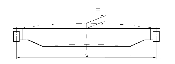
The purpose of making the main beam with a certain upward camber is to enhance its load-bearing capacity, because when the crane is lifting a load, the main beam will deflect downwards, which means that the main beam bends downwards.
2. Cantilever Upward Curvature
For the main beam of a gantry crane, in addition to the upward camber of (0.9/1000~1.4/1000)S at the mid-span of the main beam section between the two legs, if there is a cantilever outside the leg, then the upward curvature at the effective point should be (0.9/350~1.4/350)L1 (or L2) (as shown in Figure 5-10).
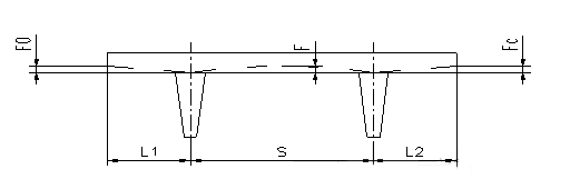
Figure 5-10 Cantilever Upward Curvature
3. Main Girder Deflection
As the service life of a bridge crane increases, the camber of the main girder gradually decreases until it disappears. The difference between the original camber and the remaining camber is the reduction in the main girder’s camber. According to rough surveys, under frequent full-load conditions, the camber disappears by about 20% after one to two years of use, about 40% after five years, and deflection generally begins to appear after about ten years. Therefore, the crane should be inspected and measured regularly during use. If the deflection exceeds the specified limit, it should be taken out of service and repaired promptly. If it cannot be repaired, it should be scrapped.
4. Main Girder Rigidity
The rigidity requirements for the main girder of bridge cranes are divided into two aspects: static rigidity.
(1) Static Rigidity
Static rigidity is expressed as the static elastic deformation value of a structure at a specified location when a specified load is applied. That is, when a fully loaded trolley (or electric hoist) is located at the mid-span of the main beam, the main beam experiences elastic deflection at mid-span due to the rated lifting load and the trolley’s own weight, which represents the magnitude of static rigidity.
Elastic deflection refers to the deflection of the main beam under load, which returns to its original state after the load is removed.
For newly installed cranes, the allowable elastic deflection requirement is: (This is for reference only; specific design should be based on relevant national standards and specifications)

(2) Dynamic Rigidity
The dynamic rigidity of a crane as a vibration system is expressed by its full-load natural frequency, which is the natural frequency of the crane under full load, with the trolley at mid-span, lowering the load at a constant speed, and undergoing emergency braking as it approaches the ground. The full-load natural frequency of a bridge crane should not be lower than 2Hz. Unless otherwise specified, dynamic rigidity measurement is not required for general bridge cranes.
III. Operator’s Cab
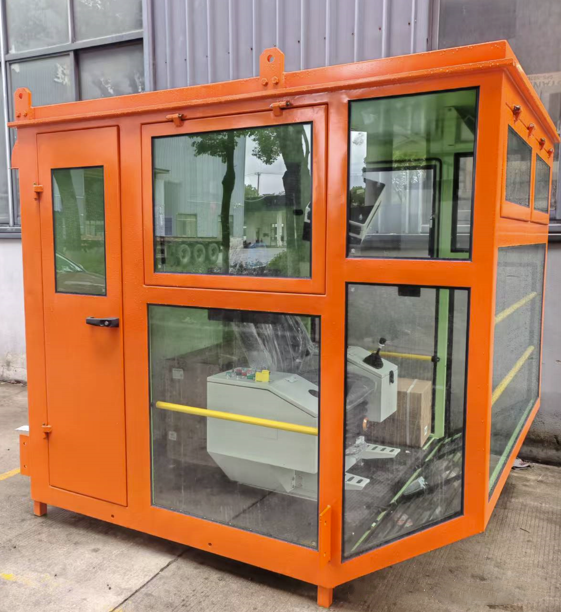
The operator’s cab contains the electrical control equipment and protective distribution panel for all crane mechanisms, emergency switches, electric bells, and lighting equipment. It is the place where the crane operator controls the operation of the crane mechanisms. The operator’s cab should be reliably suspended under the walkway near the end beam of the cable tray, generally on the side without exposed conductive wires.
IV. Trolley Traveling Mechanism
The common transmission type for the trolley traveling mechanism of general-purpose bridge cranes (as shown in Figure 5-11) is a separate drive system. The reducer output end is connected to the wheels via a gear coupling or a universal coupling for easy installation and adjustment.
Trolley wheels are mostly cylindrical double-flanged wheels. In medium and small-sized bridge cranes, half of the total number of wheels is generally used as the drive wheels in the trolley traveling mechanism.
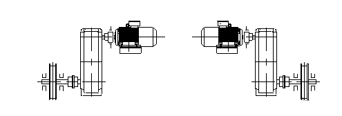
Figure 5-11 Drive device of the trolley traveling mechanism
V. Crane Trolley
The crane trolley is an important component of a bridge crane. It consists of three parts: the trolley frame, the hoisting mechanism, and the traveling mechanism (as shown in Figure 5-12). Its structural feature is that all mechanisms are composed of independently assembled components, such as the motor, reducer, brake, drum, pulley assembly, and trolley wheel set. These are all interconnected using gear couplings. The advantage of gear couplings is that they can compensate for positional errors at the shaft ends to a certain extent. This well-organized structure of the crane trolley simplifies assembly and maintenance.
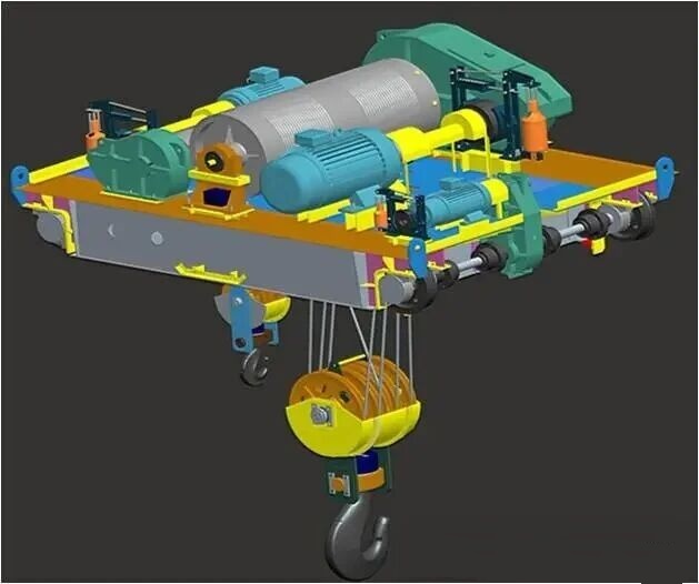
Figure 5-12 Car Diagram
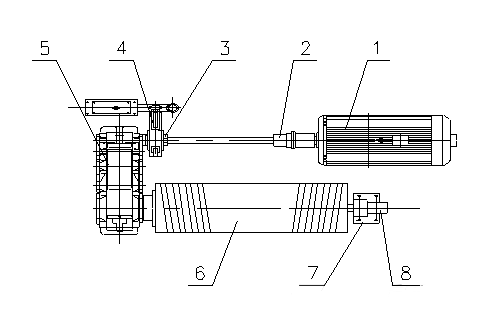
Figure 5-13 Diagram of the trolley lifting mechanism
1-Motor; 2-Coupling; 3-Brake wheel coupling; 4-Brake wheel; 5-Reducer; 6-Drum; 7-Bearing; 8-Over-winch limiter
1. Lifting Mechanism
The lifting mechanism is used to lift heavy objects. It consists of a lifting device, a wire rope winding system, and a drive unit, and is commonly arranged on the trolley (as shown in Figure 5-13).
2. Trolley Traveling Mechanism
In cranes with medium and small lifting capacities, there are two transmission forms for the trolley traveling mechanism (as shown in Figure 5-14). One type has the gearbox located between the two drive wheels (as shown in Figure 5-14a), and the other has it on one side of the trolley (as shown in Figure 5-14b). The gearbox, positioned between the two drive wheels, distributes the torque more evenly on the transmission bearings. The gearbox, positioned on one side of the trolley, facilitates installation and maintenance.
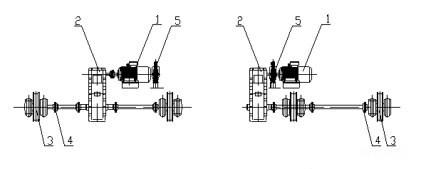
Figure 5-14 Trolley Running Mechanism
1—Motor; 2—Reducer; 3—Wheel; 4—Coupling; 5—Brake
Core Logic of Overall Machine Structural Design
The components of a crane do not exist independently. The design must adhere to the principles of functional matching, reasonable stress distribution, and safety and reliability, ensuring that the metal structure, working mechanism, and safety devices work together to meet operational requirements while guaranteeing long-term stable operation of the equipment.
Related Posts
What is an Electric Winch?
This electric winch is a motorized mechanical device. It utilizes an electric…
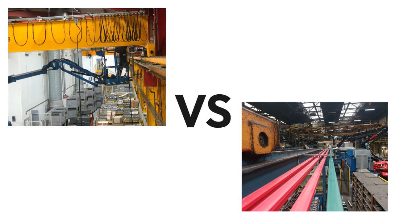
Festoon vs Conductor Bar: Which Power System for Your Overhead Crane?
Every overhead crane needs a way to deliver electrical power…